Description
There is no phase angle shift in Delta – Delta or Wye-Wye transformer. However, there is 30 degree phase angle shift in Delta-Wye transformer. Many articles take that as a fact without any explanation. Articles also state that high voltage side leads the low voltage side by 30 degree. That conclusion does not make sense to me. Below is my derivation of the phase shift.
Derivation of Delta – Wye connection phase angle shift
Transformer shown below is Delta – Wye connection.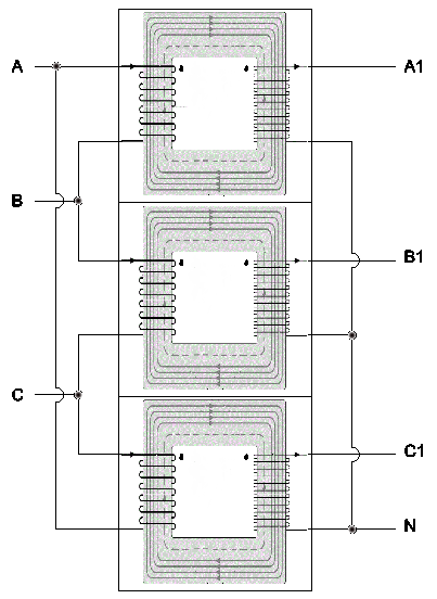
Transformer operates under Faraday’s law of induction. For an ideal transformer with 1:1 ratio between primary and secondary, voltage on the primary side should equal to that of the secondary side. Phase angle can be either same or off by 180 degree depends on coil direction. For the drawing above, primary phase angles synchronize with that of secondary’s.
The equations below are true:
VAB = VA1N – same phase
VBC = VB1N – same phase
VCA = VC1N – same phase
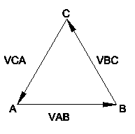
Three phase voltage and current calculations are vector calculations. Each vector has magnitude and direction. When direction is changed, sign of the vector is changed. For example, VBC = – VCB.
Vector diagram on Delta side is:
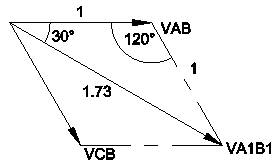
Use vector addition to calculate the phase to phase voltage on the Wye side:
VA1B1:
VA1B1 = VA1N + VNB1
= VA1N – VB1N
= VAB – VBC
= VAB + VCB
Vector addition diagram is shown below.
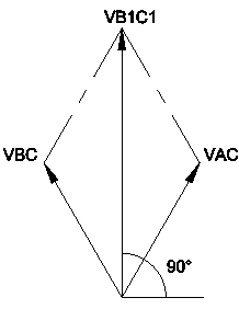
VB1C1:
VB1C1 = VB1N + VNC1
= VB1N – VC1N
= VBC – VCA
= VBC + VCA
Vector addition diagram is shown below.
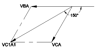
VC1A1:
VC1A1 = VC1N + VNA1
= VC1N – VA1N
= VCA – VAB
= VCA + VBA
Vector addition diagram is shown below.
These three phase to phase voltage vectors generate Wye size vector diagram below.
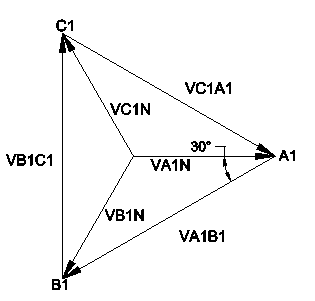
Compare it to original vector diagram at the delta side, the second vector diagram leads the primary side by 30°.
|
|
Additional Discussion
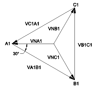
If neutral and power wires on the Wye side are swapped, second vector diagram for Wye side can be created. This vector diagram lags the primary side by 30°. Hence the phase angle shift can be leading or lagging.
Three phase current phase angles also shift across Delta – Wye connected transformer with the same rules.
|
 |