Background
General Electric’s EPM7000 power quality meter is used to monitor power consumption and power quality. EPM7000 generates phasor diagram. If the wiring between the line and meter is standard Wye-Wye, Delta-Delta or Delta – Wye connection, the phasor diagram is easy to read. However, the phasor diagram is very confusing on 2CT, Delta connection. EPM7000’s phasor diagram does not show all three phases. It also inverts one of two vectors it shows. This article attempts to provide a quick reference for field phasor check. Any related recommendation and comments are welcomed.
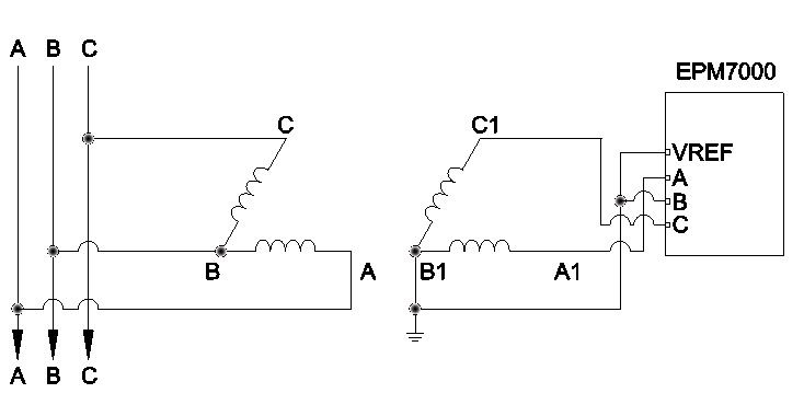
Wirings
The EPM7000 are wired as shown below. EPM7000 voltage input is wired as open delta to open delta:
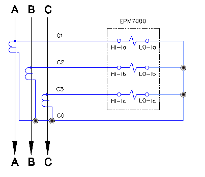
Current input is wired as delta to wye:
 ABC rotation phasor diagram and power factor calculation
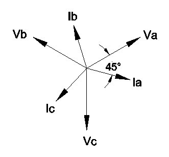
EPM7000 is configured as Delta, 2CTs. EPM7000 generated phasor Diagram for ABC rotation is shown below. Vector Ia lags vector Vab by 52.50 degree.
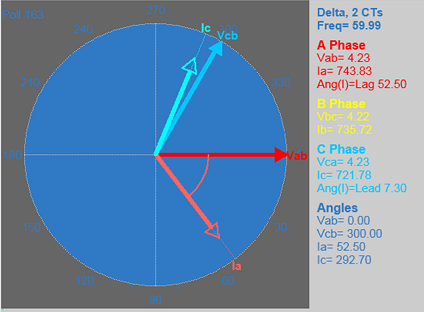
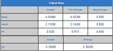
EPM7000 calculated Power Factor for ABC rotation is captured below:
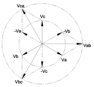
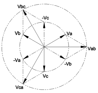
Is this ABC rotation phasor diagram correct? This phasor diagram is not very intuitive to judge its correctness. To judge the correctness of the phasor diagram, phase-to-phase voltage phasor diagram should be dis-constructed into phase-to-ground voltage phasor diagram. With vector algebra, Vcb = -Vbc, and Vab = Va + (-Vb), phase to ground vector phasor diagram is shown below. Vector Va is 30 degree behind vector Vab in ABC rotation phasor.
The Delta-to-Wye current transformer connection sends each phase to phase current to individual element in EPM7000. Current phasor diagram can be used directly without dis-construction. ABC rotation phase-to-ground current phasor diagram is shown below:
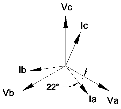
Ia lags behind Vab by 52.50 degree from EPM7000’s phasor diagram.Va lags Vab by 30 degree. Angle between Va and Ia is 22.50 degree (22.50 = 52.50- 30). Displacement power factor is defined as cosine of the angle between Va and Ia.
Displacement power factor = cosine (22.50) = 0.924
EPM7000 calculated power factor = (instant watt)/sqrt( (instant watt)^2 + (vars)^2 ) = 4.938 / sqrt (4.938^2 + 2.11^2) = 0.918
Displacement power factor of 0.924 is very close to EPM7000’s calculated power factor 0.920.
ABC rotation phasor diagram conclusion
This phasor diagram from EPM7000 for ABC rotation is correct. Hence all wirings for this EPM7000 are correct.
ACB Rotation Phasor diagram and Power Factor
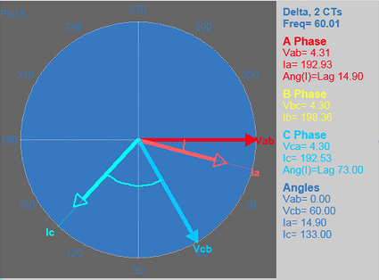
EPM7000 generated ACB rotation phasor diagram. Vector Ia lags vector Vab by 14.9 degree.
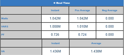
EPM7000 generated ACB rotation power factor is captured below:
Just as ABC roation, the phase-to-phase voltage phasor diagram is dis-constructed to phase-to-ground voltage phasor diagram. ACB rotation phase-to-ground dis-constructed voltage phasor diagram is shown below. Vector Va leads vector Vab by 30 degree.
ACB current phasor diagram is constructed below.
Ia lags behind Vab by 14.9 degree from EPM7000’s phasor diagram.Va leads Vab by 30 degree. Angle between Va and Ia is 44.9 degree (44.9 = 14.9 + 30). Displacement power factor is defined as cosine of the angle between Va and Ia.
Displacement power factor = cosine (44.9) = 0.708
EPM7000 calculated power factor = (instant watt)/sqrt( (instant watt)^2 + (vars)^2 ) = 1.042 / sqrt (1.042^2 + 1.008^2) = 0.718
Displacement power factor of 0.708 is very close to EPM7000’s calculated power factor 0.72.
ACB rotation phasor diagram conclusion
This phasor diagram from EPM7000 for ACB rotation is correct. Hence all wirings for this EPM7000 are correct.